
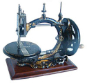
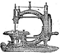

Figure 2
The Pope Darning Machine (late 1870s)
The Darning Machine
Jennifer & Martin Gregory
A generation and more ago, most people mended socks and hosiery when they wore through so that darning aids had a ready sale. In today's world, most people buy the latest fashion and discard clothes long before they are worn out. When did you last darn tights or socks?
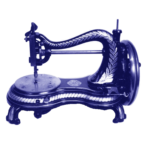
There are plenty of patents for darning machines and a few of these were developed into saleable machines. One of these was 'The Darning Machine' made by the Pope Manufacturing Company of Boston. Figure 1 (below) shows an advertisement from the Sewing Machine Journal of September 1877). The machine (Figs. 2 & 3) was the brainchild of Oren Stanley Hosmer of Boston, MA. He patented it in the USA on 25th August 1874 (No. 154483) followed by improvements on 13th April 1875 (No 162028) and 27th April 1875 (No. 162656).
The machine was also patented in Canada, England (No. 3941 of 16th November, 1874), France and Belgium. Fig. 4 shows a diagram from the 1874 American patent. It must have been one of the first products of the Pope Manufacturing Company, founded in 1877 and maker of the famous 'Columbia' bicycle
Hosmer's patent was for a 'simple and inexpensive machine by which the darning of stockings may be effected with a minimum of the time and labour now employed for the purpose.' The fabric is clamped between two circular brass discs 30 mm in diameter, with inter-digitating grooves, so that the clamped fabric is folded into ridges through which the needles pass. The needle bar carries 14 needles which can pass through the folded fabric. The needles are threaded (all the eyes are aligned) with the needle bar retracted. Rotating the handle pushes the needles through the folded fabric (Fig. 5).


Figure 4
Hosmer's American patent drawing (1874)
Emerging on the other side the loops cast off by the needles are hooked round the comb using a crochet hook (Fig. 6). When the needles are retracted 28 lines of thread are left spanning the hole.
The fabric is then released, rotated through 90o and then re-clamped into folds perpendicular to the initial set. Pushing the needles through and retaining the loops again leaves a 28 by 28 woven patch!
"In darning with this machine," claims the inventor, "I do not produce irregular, hard or unsightly lumps and ridges, which is the result of darning by hand; but, on the contrary, I produce a new textile fabric which is pliable, soft and fully equal in appearance, ease and desirability to the original material." Experiments with our machine suggest that a very careful choice of fabric, thread and hole, together with a lot of practice, would be necessary to substantiate that claim. It definitely takes a lot longer to use Hosmer's machine than to darn by hand: threading all the needles; picking off a loop from each needle onto the comb; and, when the needles are retracted, cutting all the threads to enable one to rotate the cloth by 90o before rethreading all the needles again. (Fig. 7 shows the half-way stage).

Figure 5
The needle arrangement of Hosmer's machine

Figure 6
Needle and comb arrangement

Figure 3
The Pope Darning Machine
The patent application ends: 'Although my present machine, as originally devised, was intended for darning stockings, I am enabled to adapt it for a variety of useful purposes. For instance, I am enabled to weave lamp-mats, chair tidies and many ornamental and useful articles of a size equal to the area of the plunger.' With an area equal to that of a circle of diameter 30 mm, was he perhaps furnishing a dolls' house?
One can darn using a traditional lock stitch sewing machine by covering over the feed dog and steering the fabric by hand so that it stitches over and over the thin area. As an aid, Clark & Co, Ltd produced mercerised cotton squares for darning and patching using a sewing machine (Fig. 8).
The instructions read: "Cut a hole, square or oblong, slightly smaller than the Darning patch and machine round the edge of the hole once or twice to keep the shape. Now place the patch on top, taking care that the threads are placed parallel with the weave of the material and machine all round, before commencing to stitch backwards and forwards across the threads. When the patch is completely filled in, cut away the ends as closely as possible to the stitching."

Figure 7
Sample of stage one with the Hosmer machine
As late as the 1950s, such darning machines which attempted to weave a patch over the hole were still being patented. The 'Speedweve' darner appeared in 1950 (Figs. 9 & 10, pp20). It claimed to be patented in Great Britain, Canada, U.S.A., South Africa, Australia and New Zealand. The sock (in the illustration) was stretched over a wooden mushroom (the traditional darning aid) and an ordinary long darning needle used to set up the 'warp' round the hooks on the machine. The same needle was used as a 'shuttle' for the 'weft'. Sliding the strip AB (Fig. 10) reversed the hooks to reverse the shed, as is done by the healds on a loom. No claims are made in the instructions for applications other than for darning socks and other coarse materials. (J&M G)

Figure 10
The 'Speedweeve' darner

Figure 8
Clark's mercerised cotton squares

Figure 9
The 'Speedweve' instructions