Davis Vertical Feed attachments
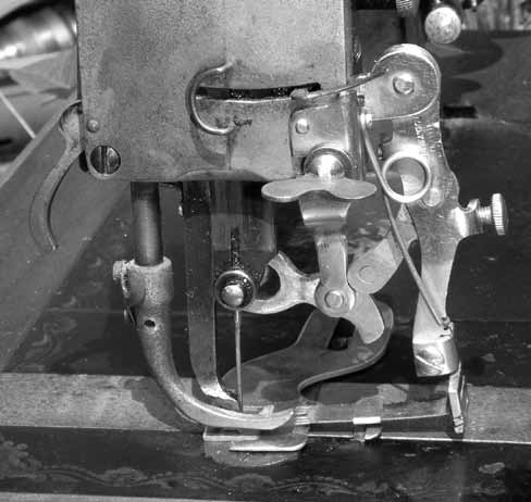
Figure 1
Showing the ruffler in situ, suspended from above, with its lower plate bolted down to the bed-plate. Having more than one fixing point also allowed for other attachments to be used in conjunction with the ruffler; including a very intricate device for decorating scallop edges (see below).
The needle feed system used by the Davis Company in its V.F. domestic machines provided a reliable, positive action that 'pushed' the goods under the presser foot while the needle was in the material.
Conventional drop feed systems, that relied solely on feed dogs to propel the material, needed to have the needle clear of the fabric for the feed to work which, especially with heavy or slippery cloths, often led to uneven feeding. Unless finely adjusted, the top layer is inevitably impeded by friction from the presser foot.
The Davis arrangement did much to eliminate this 'creep' while elegantly avoiding the necessity to license A.B. Wilson's four motion feed, used (at considerable cost) by most other manufacturers. Davis' presser foot was really two feet: one kept downward pressure on the material long enough to form the stitch before rising to permit the second 'foot' (in conjunction with the needle) to push the material forwards.
However, having to avoid a needle that is moving in two planes caused extra problems for those who designed the Davis attachments; many of which are fixed, not to the presser foot, but suspended from the face-plate end of the arm, just above the needle.
Curiously, there are several methods for attaching hemmers and binders to the Davis V.F. Some of the hemmers are fixed to the base-plate in the 'traditional' way; the bias binder hangs suspended from the face plate and several of the hemmers are permanently mounted on replaceable shuttle slide cover plates, used in place of the slider that normally bears the serial number and patent details. There is no mention of this latter type in the various manuals and even though they fit and work, they bear no maker's mark and I can only assume they are original.
John Langdon
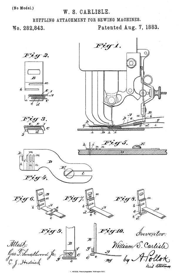
Figure 2
W. S. Carlisle's patent drawing of 1883 (Fig. 2) shows the components of the ruffler, the main advantage of which was the provision of extra sliding edge guides to allow several layers of material to be sewn at once.
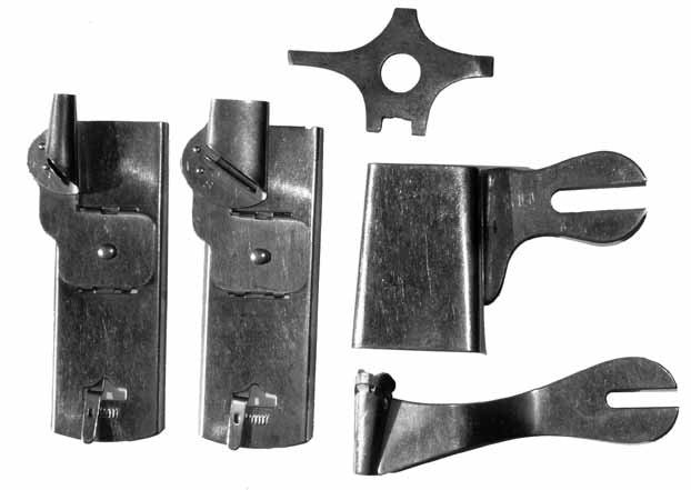
Three methods of attachment; shuttle slide cover replacements, a bed-mounted wide hemmer, face-plate
mounted binder and (top) Davis' screwdriver.
Bottom right: the Davis scallop plaiter a $3 optional extra.
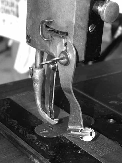
The Binder in Position
The presser foot comprises two parts, like an industrial vibrating (walking) foot.
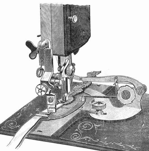
A very intricate device for decorating scallop edges, shown mounted in conjunction with the ruffler from Figure 1, above.
